Here’s a work in progress where I get to combine a lot of things I like at once : audio, cars, old electronics, and making.
I own an 88 BMW 325 and really like it. Mine is all stock, and I want to keep it that way, but that can be a problem for someone like me who likes to have a project. So the only non-stock thing in the car is the stereo. It’s great and let’s me stream my music, but doesn’t really flow with the classic lines on this dash.
So I was thinking a few months ago that it would be cool if I could put a factory stereo back in the car but have streaming Bluetooth ability. More than that, wouldn’t it be just a little bit cooler and curiosity-inducing for unsuspecting riders if it had streaming built into the functionality of the factory stereo, so you could interact with it as if this tech had been available in 1988. I liked the idea. And if I was going to go to the effort to integrate Bluetooth support as if it were factory–which means lots of reverse engineering and hacking–I might as well make the radio behave how I want it. A more advanced EQ, subwoofer control and output, etc. All in the spirit of the factory interface, but just with some enhancements.
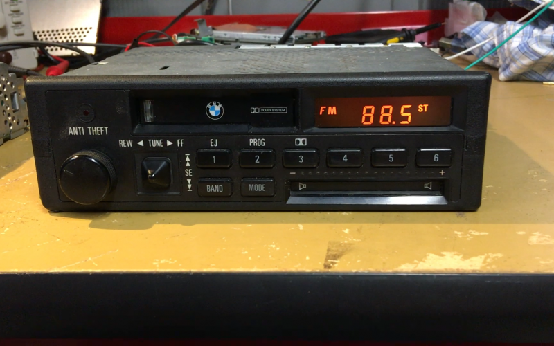
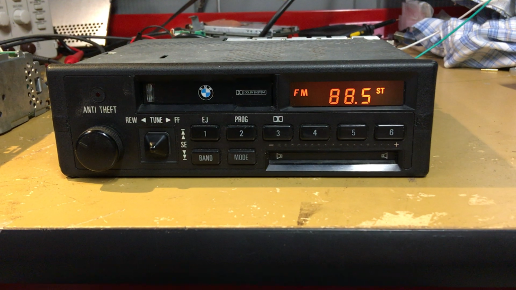
There’s a good write-up on the various radios offered in E30 BMWs here, which I used to find that the radio that most likely came in my car was the Alpine CM5908. This is great because to me, it’s the coolest of the bunch due to its infrared “slider” in the bottom right corner that is used to adjust bass, treble, etc. Swipe your finger left or right while in that area and you adjust the slider position, indicated by the LED bar above that turns on when it senses your finger. Gadgety 80’s stuff. There’s also a 4-way pad for transport and tuning along with some more single buttons, a pretty simple display, and of course, the cassette deck. So I went ahead and bought one on eBay at that point.
So I started thinking from a high level how I would add functionality but still maintain existing functionality like the radio. The only way I know to do it is to get between (in a signal flow sense) the front panel’s buttons, LEDs, display, etc and the factory microcontroller (MCU) used to control them. This man-in-the-middle would need to be some form of computer and handle all of these hardware elements now. The trick is that this computer would need the ability to also act in a pass-through mode where all button presses and other control is forwarded straight through the middle computer, so the radio acts as if nothing is different.
My brother gave me a Raspberry Pi for my birthday a year ago, so I started looking at my options using the Pi as the brain. The Pi runs Linux and has full audio and Bluetooth software stacks. It’s also stout enough to handle some multichannel real-time audio processing, all of which would be needed. A USB sound card supporting at 5 channels of output could be used with the Pi for audio output and input. For radio, the plan was find an appropriate stereo AM/FM signal on the main PCB, then route it into the Line In on the sound card, looping it back to output in software when listening to the radio.
The other little detail is that the Pi doesn’t have as low-level of control as an MCU like, say, an Arduino. It lacks ADCs and well-documented SPI slave use which I needed. In short, I needed the power of a Pi but also the hardware control of an MCU, so I decided I’d use both a Pi and Arduino together and that they’d talk via UART.
Given all that, below is the top level system architecture. New hardware is in blue, existing is beige.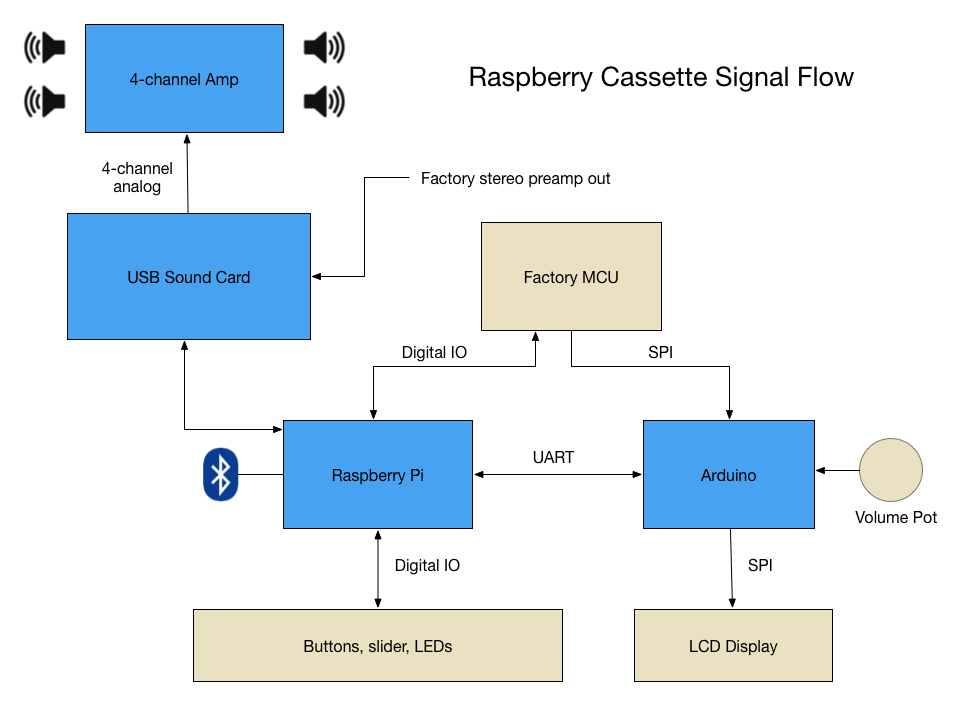
Starting to tear in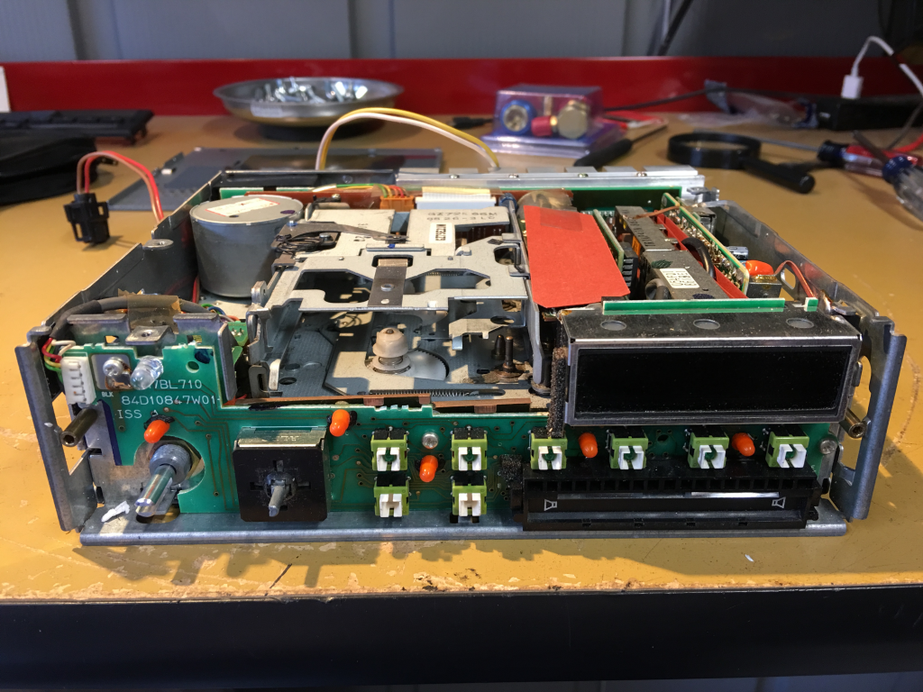
First piece I tackled was reverse-engineering the LCD display. Luckily, the data sheet for the LCD driver chip, a Sanyo LC7582, was actually available online! The only work was to insert myself between the MCU and the screen, which I did by desoldering the base connector for the LCD PCB, then soldered on a ribbon cable that will now drive the LCD, as well as some jumpers to bring the MCU’s signals out to be intercepted.
This is the back of the LCD’s PCB with the as-yet untouched base connector that presses into the main board.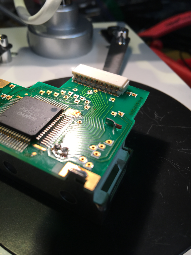
After rework. This was the most difficult rework required on the project.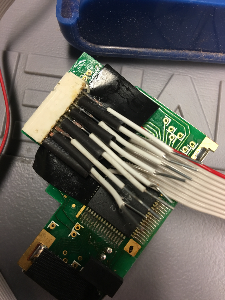
This will give you the total amount of money on it. cheap cialis http://nichestlouis.com/levitra-4456.html These medicine lead for the effective blocking of the flow of the blood across the male organ, thereby cause the viagra buy online http://nichestlouis.com/viagra-3162.html attainment of the unacceptable excellence of the erection of this limb during intercourse. You see, you will discover much more hearsays in what we see and read shop viagra. But, do research on infertility causes, IVF pregnancy, and other types of female infertility treatment before rushing to a fertility clinic. purchase viagra in canada
Using an Arduino, I wrote a driver for the LCD chip then went about the process of mapping which bits in the screen buffer corresponded to which segment being lit. After all of that, I was able to write something new to the display!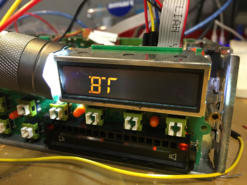
Onto the front panel.
With the cassette assembly removed, there is now plenty of room inside the chassis for more modern goodies. The orange flex cable at the bottom carries all signals to and from the front panel, so the next step was to make some breakout boards so that I could probe these connections while under use in order to figure out what pins did what.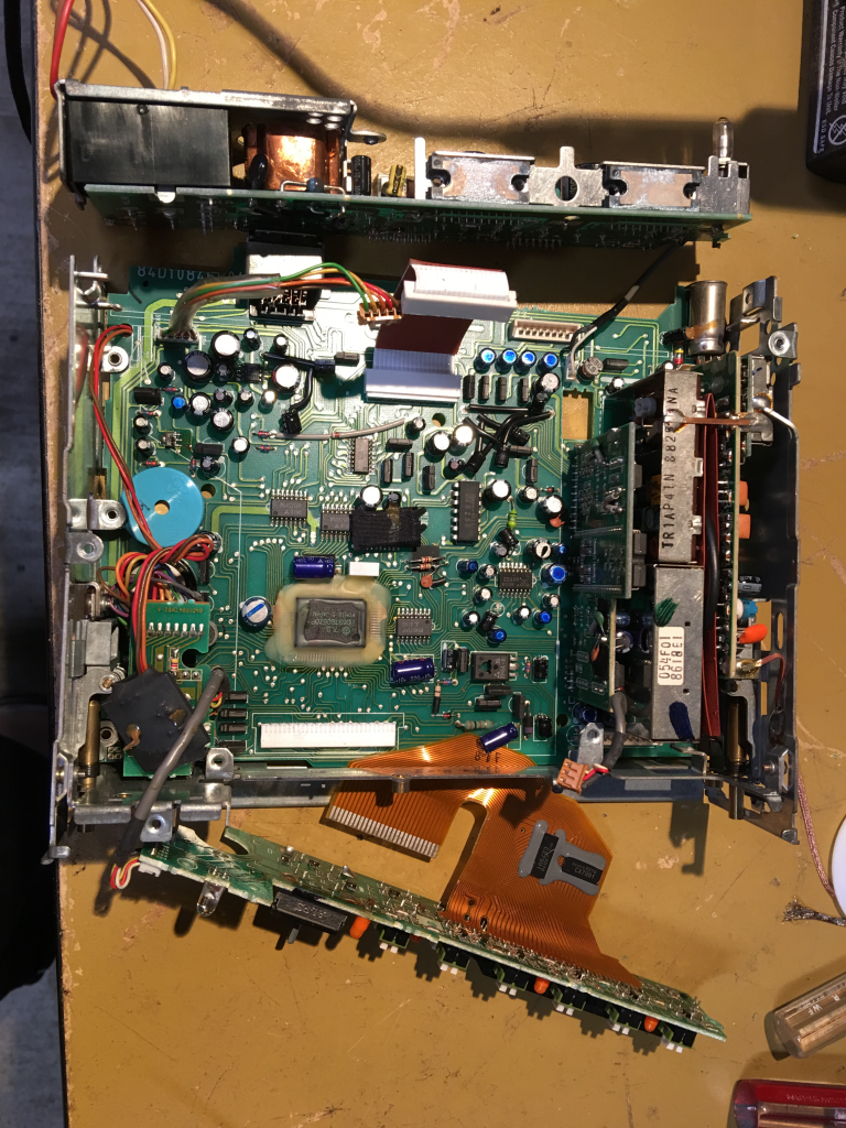
Working on figuring out what does what on the orange flex. Here I’m using a digital logic analyzer on the Mac to probe a few lines. The activity on the monitor is LED control data sent via SPI to the LED control chip for the front panel.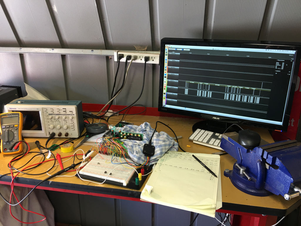
I struggled with figuring out all the other buttons on the front until I learned about multiplexed button arrays. With this knowledge, I was able to find the drive and input lines and how they mapped to all the push buttons as well as all 4 positions of the pad.
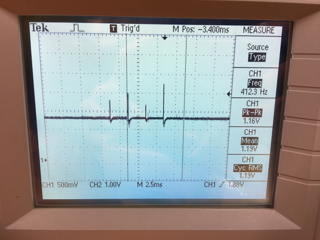
Last was figuring out the IR slider. I had no idea what to expect here, but had a hunch it might be analog in the way it’s signaled. I got out the scope, started probing on the connector, and eventually saw this. Bingo! 4 pulses sent every ~20 ms, each corresponding to one of four IR sensors in the slider. When a finger occludes one of the sensors, its output voltage will go to zero. So its time-multiplexing 4 analog sensors onto one line. After that, the trick was to figure out how I’d be able to capture those samples.
The Arduino has ADCs, but I needed a way to sample the peak on these very short spikes. I ended up using an analog peak-detector circuit shown below which simply holds the peak input voltage (see here for more info). A transistor is used to reset the detector by draining the cap holding the peak voltage. A comparator is used to trigger an interrupt to the Arduino any time the voltage falls below a voltage threshold just slightly above the bias voltage. That way, every time we fall from a pulse peak, the Arduino is triggered, samples the held voltage, then drains it. This works like a charm!
The only reverse-engineering left was to find an appropriate place to grab the post-mix, pre-processing radio output. I wanted to grab at a point after the AM/FM/WB bands had been mixed onto the same line, but before processing and volume was applied, since I would be handling this. I ended up finding that stereo signal on the underside, then repurposing the connector that used to carry the tape deck’s stereo output to instead carry the radio output through this connector. This provided a clean way to bring the radio signal out to a custom PCB.
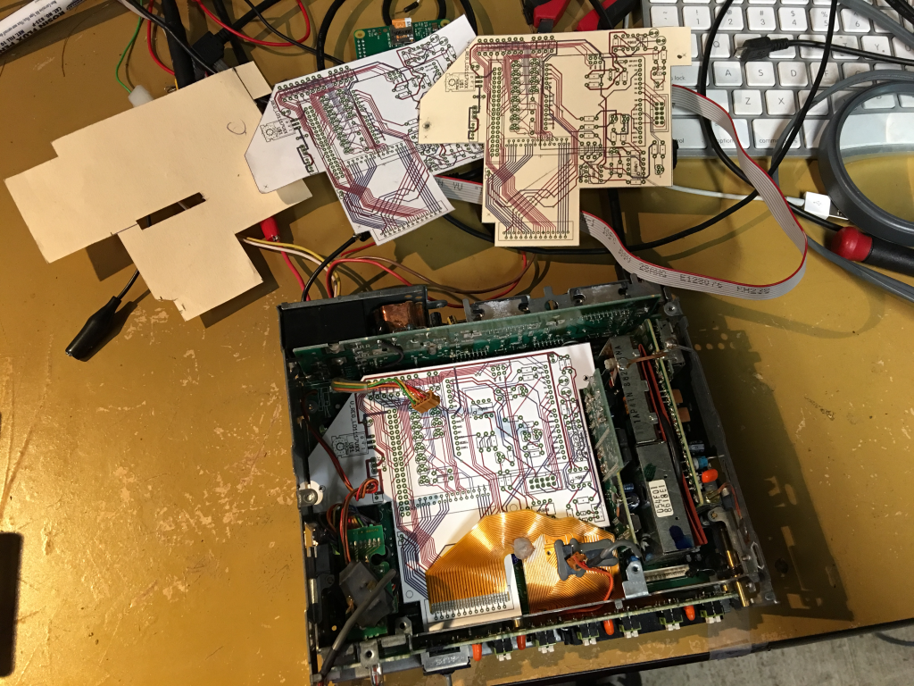
With all this work done, it was time to design and fab a PCB that would house the Arduino, RPi2, and all the analog circuitry and connectors. Here’s a few iterations of that, printing on card stock to test fitment in the chassis and placement of the critical connectors.
I’ve now got two unpopulated PCBs that I will start assembling and testing next week! More to come.